![]()
The Border Gateway Protocol (BGP), defined in RFC 1771, allows you to create loop free interdomain routing between autonomous systems. An autonomous system is a set of routers under a single technical administration. Routers in an AS can use multiple interior gateway protocols to exchange routing information inside the AS and an exterior gateway protocol to route packets outside the AS.
BGP uses TCP as its transport protocol (port 179). Two BGP speaking routers form a TCP connection between one another (peer routers) and exchange messages to open and confirm the connection parameters.
BGP routers will exchange network reachability information, this information is mainly an indication of the full paths (BGP AS numbers) that a route should take in order to reach the destination network. This information will help in constructing a graph of ASs that are loop free and where routing policies can be applied in order to enforce some restrictions on the routing behavior.
Any two routers that have formed a TCP connection in order to exchange BGP routing information are called peers, they are also called neighbors.
BGP peers will initially exchange their full BGP routing tables. From then on incremental updates are sent as the routing table changes. BGP keeps a version number of the BGP table and it should be the same for all of its BGP peers. The version number will change whenever BGP updates the table due to some routing information changes. Keepalive packets are sent to ensure that the connection is alive between the BGP peers and notification packets are sent in response to errors or special conditions.
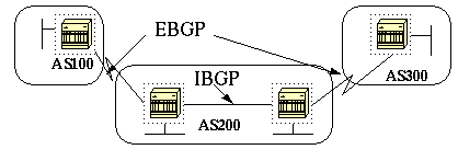
If an Autonomous System has multiple BGP speakers, it could be used as a transit service for other ASs. As you see below, AS200 is a transit autonomous system for AS100 and AS300.
It is necessary to ensure reachability for networks within an AS before sending the information to other external ASs. This is done by a combination of Internal BGP peering between routers inside an AS and by redistributing BGP information to Internal Gateway Protocols running in the AS.
As far as this paper is concerned, when BGP is running between routers belonging to two different ASs we will call it EBGP (Exterior BGP) and for BGP running between routers in the same AS we will call it IBGP (Interior BGP).
Here are the steps needed to enable and configure BGP.
Let us assume you want to have two routers RTA and RTB talk BGP. In the first example RTA and RTB are in different autonomous systems and in the second example both routers belong to the same AS.
We start by defining the router process and define the AS number that the routers belong to. The command used to enable BGP on a router is:
router bgp autonomous-system
RTA#
router bgp 100
RTB#
router bgp 200
The above statements indicates that RTA is running BGP and it belongs to AS100 and RTB is running BGP and it belongs to AS200 and so on.
The next step in the configuration process is to define BGP neighbors. The neighbor definition indicates which routers we are trying to talk with BGP.
The next section will introduce you to what is involved in forming a valid peer connection.
Two BGP routers become neighbors or peers once they establish a TCP connection between one another. The TCP connection is essential in order for the two peer routers to start exchanging routing updates.
Two BGP speaking routers trying to become neighbors will first bring up the TCP connection between one another and then send open messages in order to exchange values such as the AS number, the BGP version they are running (version 3 or 4), the BGP router ID and the keepalive hold time, etc. After these values are confirmed and accepted the neighbor connection will be established. Any state other than established is an indication that the two routers did not become neighbors and hence the BGP updates will not be exchanged.
The neighbor command used to establish a TCP connection is:
neighbor ip-address remote-as number
The remote-as number is the AS number of the router we are trying to connect to via BGP.
The ip-address is the next hop directly connected address for EBGP and any IP address on the other router for IBGP.
It is essential that the two IP addresses used in the neighbor command of the peer routers be able to reach one another. One sure way to verify reachability is an extended ping between the two IP addresses, the extended ping forces the pinging router to use as source the IP address specified in the neighbor command rather than the IP address of the interface the packet is going out from.
It is important to reset the neighbor connection in case any bgp configuration changes are made in order for the new parameters to take effect.
clear ip bgp address (where address is the neighbor address)
clear ip bgp * (clear all neighbor connections)
By default, BGP sessions begin using BGP Version 4 and negotiating downward to earlier versions if necessary. To prevent negotiations and force the BGP version used to communicate with a neighbor, perform the following task in router configuration mode:
neighbor {ip address|peer-group-name} version value
An example of the neighbor command configuration follows:
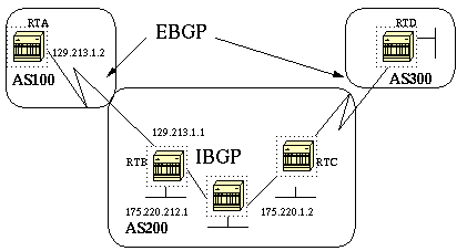
RTA#
router bgp 100
neighbor 129.213.1.1 remote-as 200
RTB#
router bgp 200
neighbor 129.213.1.2 remote-as 100
neighbor 175.220.1.2 remote-as 200
RTC#
router bgp 200
neighbor 175.220.212.1 remote-as 200
In the above example RTA and RTB are running EBGP. RTB and RTC are running IBGP. The difference between EBGP and IBGP is manifested by having the remote-as number pointing to either an external or an internal AS.
Also, the EBGP peers are directly connected and the IBGP peers are not. IBGP routers do not have to be directly connected, as long as there is some IGP running that allows the two neighbors to reach one another.
The following is an example of the information that the command "sh ip bgp neighbors" will show you, pay special attention to the BGP state. Anything other than state established indicates that the peers are not up. You should also note the BGP is version 4, the remote router ID (highest IP address on that box or the highest loopback interface in case it exists) and the table version (this is the state of the table, any time new information comes in, the table will increase the version and a version that keeps incrementing indicates that some route is flapping causing routes to keep getting updated).
#SH IP BGP N
BGP neighbor is 129.213.1.1, remote AS 200, external link
BGP version 4, remote router ID 175.220.12.1
BGP state = Established, table version = 3, up for 0:10:59
Last read 0:00:29, hold time is 180, keepalive interval is 60 seconds
Minimum time between advertisement runs is 30 seconds
Received 2828 messages, 0 notifications, 0 in queue
Sent 2826 messages, 0 notifications, 0 in queue
Connections established 11; dropped 10
In the next section, we will discuss special situations such as EBGP multihop and loopback addresses.
Using a loopback interface to define neighbors is commonly used with IBGP rather than EBGP. Normally the loopback interface is used to make sure that the IP address of the neighbor stays up and is independent of a hardware that might be flaky. In the case of EBGP, most of the time the peer routers are directly connected and loopback does not apply.
If the IP address of a loopback interface is used in the neighbor command, some extra configuration needs to be done on the neighbor router. The neighbor router needs to tell BGP that it is using a loopback interface rather than a physical interface to initiate the BGP neighbor TCP connection. The command used to indicate a loopback interface is:
neighbor ip-address update-source interface
The following example should illustrate the use of this command.

RTA#
router bgp 100
neighbor 190.225.11.1 remote-as 100
neighbor 190.225.11.1 update-source int loopback 1
RTB#
router bgp 100
neighbor 150.212.1.1 remote-as 100
In the above example, RTA and RTB are running internal BGP inside autonomous system 100. RTB is using in its neighbor command the loopback interface of RTA (150.212.1.1); in this case RTA has to force BGP to use the loopback IP address as the source in the TCP neighbor connection. RTA will do so by adding the update-source int loopback configuration (neighbor 190.225.11.1 update-source int loopback 1) and this statement forces BGP to use the ip address of its loopback interface when talking to neighbor 190.225.11.1.
Note that RTA has used the physical interface IP address (190.225.11.1) of RTB as a neighbor and that is why RTB does not need to do any special configuration.
In some special cases, the Cisco router could be running external BGP with a third party router that does not allow the two external peers to be directly connected. In this case EBGP multihop is used to allow the neighbor connection to be established between two non directly connected external peers. The multihop is used only for external BGP and not for internal BGP. The following example gives a better illustration of EBGP multihop.

RTA#
router bgp 100
neighbor 180.225.11.1 remote-as 300
neighbor 180.225.11.1 ebgp-multihop
RTB#
router bgp 300
neighbor 129.213.1.2 remote-as 100
RTA is indicating an external neighbor that is not directly connected. RTA needs to indicate that it will be using ebgp-multihop. On the other hand, RTB is indicating a neighbor that is directly connected (129.213.1.2) and that is why it does not need the ebgp-multihop command. Some IGP or static routing should also be configured in order to allow the non connected neighbors to reach eachother.
The following example shows how to achieve load balancing with BGP in a particular case where we have EBGP over parallel lines.
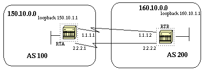
RTA#
int loopback 0
ip address 150.10.1.1 255.255.255.0
router bgp 100
neighbor 160.10.1.1 remote-as 200
neighbor 160.10.1.1 ebgp-multihop
neighbor 160.10.1.1 update-source loopback 0
network 150.10.0.0
ip route 160.10.0.0 255.255.0.0 1.1.1.2
ip route 160.10.0.0 255.255.0.0 2.2.2.2
RTB#
int loopback 0
ip address 160.10.1.1 255.255.255.0
router bgp 200
neighbor 150.10.1.1 remote-as 100
neighbor 150.10.1.1 update-source loopback 0
neighbor 150.10.1.1 ebgp-multihop
network 160.10.0.0
ip route 150.10.0.0 255.255.0.0 1.1.1.1
ip route 150.10.0.0 255.255.0.0 2.2.2.1
The above example illustrates the use of loopback interfaces, update-source and ebgp-multihop. This is a workaround in order to achieve load balancing between two EBGP speakers over parallel serial lines. In normal situations, BGP will pick one of the lines to send packets on and load balancing would not take place. By introducing loopback interfaces, the next hop for EBGP will be the loopback interface. Static routes (it could be some IGP also) are used to introduce two equal cost paths to reach the destination. RTA will have two choices to reach next hop 160.10.1.1: one via 1.1.1.2 and the other one via 2.2.2.2 and the same for RTB.
At this point I would like to introduce route maps because they will be used heavily with BGP. In the BGP context, route map is a method used to control and modify routing information. This is done by defining conditions for redistributing routes from one routing protocol to another or controlling routing information when injected in and out of BGP. The format of the route map follows:
route-map map-tag [[permit | deny] | [sequence-number]]
The map-tag is just a name you give to the route-map. Multiple instances of the same route map (same name-tag) can be defined. The sequence number is just an indication of the position a new route map is to have in the list of route maps already configured with the same name.
For example, if I define two instances of the route map, let us call it MYMAP, the first instance will have a sequence-number of 10, and the second will have a sequence number of 20.
route-map MYMAP permit 10
(first set of conditions goes here.)
route-map MYMAP permit 20
(second set of conditions goes here.)
When applying route map MYMAP to incoming or outgoing routes, the first
set of conditions will be applied via instance 10. If the first set of
conditions is not met then we proceed to a higher instance of the route
map.
For example, I could define a route map that checks outgoing updates and if there is a match for IP address 1.1.1.1 then the metric for that update will be set to 5. The above can be illustrated by the following commands:
match ip address 1.1.1.1
set metric 5
Now, if the match criteria are met and we have a permit then the routes will be redistributed or controlled as specified by the set action and we break out of the list.
If the match criteria are met and we have a deny then the route will not be redistributed or controlled and we break out of the list.
If the match criteria are not met and we have a permit or deny then the next instance of the route map (instance 20 for example) will be checked, and so on until we either break out or finish all the instances of the route map. If we finish the list without a match then the route we are looking at will not be accepted nor forwarded.
One restriction on route maps is that when used for filtering BGP updates (as we will see later) rather than when redistributing between protocols, you can NOT filter on the inbound when using a "match" on the ip address. Filtering on t he outbound is OK.
The related commands for match are:
match as-path
match community
match clns
match interface
match ip address
match ip next-hop
match ip route-source
match metric
match route-type
match tag
The related commands for set are:
set as-path
set clns
set automatic-tag
set community
set interface
set default interface
set ip default next-hop
set level
set local-preference
set metric
set metric-type
set next-hop
set origin
set tag
set weight
Let's look at some route-map examples:
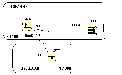
Example 1:
Assume RTA and RTB are running rip; RTA and RTC are running BGP. RTA is getting updates via BGP and redistributing them to rip. If RTA wants to redistribute to RTB routes about 170.10.0.0 with a metric of 2 and all other routes with a metric of 5 then we might use the following configuration:
RTA#
router rip
network 3.0.0.0
network 2.0.0.0
network 150.10.0.0
passive-interface Serial0
redistribute bgp 100 route-map SETMETRIC
router bgp 100
neighbor 2.2.2.3 remote-as 300
network 150.10.0.0
route-map SETMETRIC permit 10
match ip-address 1
set metric 2
route-map SETMETRIC permit 20
set metric 5
access-list 1 permit 170.10.0.0 0.0.255.255
In the above example if a route matches the IP address 170.10.0.0 it will have a metric of 2 and then we break out of the route map list. If there is no match then we go down the route map list which says, set everything else to metric 5. It is always very important to ask the question, what will happen to routes that do not match any of the match statements because they will be dropped by default.
Example 2:
Suppose in the above example we did not want AS100 to accept updates about 170.10.0.0. Since route maps cannot be applied on the inbound when matching based on an ip address, we have to use an outbound route map on RTC:
RTC#

router bgp 300
network 170.10.0.0
neighbor 2.2.2.2 remote-as 100
neighbor 2.2.2.2 route-map STOPUPDATES out

route-map STOPUPDATES permit 10
match ip address 1

access-list 1 deny 170.10.0.0 0.0.255.255
access-list 1 permit 0.0.0.0 255.255.255.255
Now that you feel more comfortable with how to start BGP and how to define a neighbor, let's look at how to start exchanging network information.
There are multiple ways to send network information using BGP. I will
go
through these methods one by one.
The format of the network command follows:
network network-number [mask network-mask]
The network command controls what networks are originated by this box. This is a different concept from what you are used to configuring with IGRP and RIP. With this command we are not trying to run BGP on a certain interface, rather we are trying to indicate to BGP what networks it should originate from this box. The mask portion is used because BGP4 can handle subnetting and supernetting. A maximum of 200 entries of the network command are accepted.
The network command will work if the network you are trying to advertise is known to the router, whether connected, static or learned dynamically.
An example of the network command follows:
RTA#
router bgp 1
network 192.213.0.0 mask 255.255.0.0
ip route 192.213.0.0 255.255.0.0 null 0
The above example indicates that router A, will generate a network entry for 192.213.0.0/16. The /16 indicates that we are using a supernet of the class C address and we are advertizing the first two octets (the first 16 bits).
Note that we need the static route to get the router to generate 192.213.0.0 because the static route will put a matching entry in the routing table.
The network command is one way to advertise your networks via BGP. Another way is to redistribute your IGP (IGRP, OSPF, RIP, EIGRP, etc.) into BGP. This sounds scary because now you are dumping all of your internal routes into BGP, some of these routes might have been learned via BGP and you do not need to send them out again. Careful filtering should be applied to make sure you are sending to the internet only routes that you want to advertise and not everything you have. Let us look at the example below.
RTA is announcing 129.213.1.0 and RTC is announcing 175.220.0.0. Look at RTC's configuration:
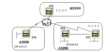
If you use a network command you will have:
RTC#
router eigrp 10
network 175.220.0.0
redistribute bgp 200
default-metric 1000 100 250 100 1500
router bgp 200
neighbor 1.1.1.1 remote-as 300
network 175.220.0.0 mask 255.255.0.0 (this will limit the networks originated
by your AS to 175.220.0.0)
If you use redistribution instead you will have:
RTC#
router eigrp 10
network 175.220.0.0
network 175.220.0.0
redistribute bgp 200
default-metric 1000 100 250 100 1500
router bgp 200
neighbor 1.1.1.1 remote-as 300
redistribute eigrp 10 (eigrp will inject 129.213.1.0 again into BGP)
This will cause 129.213.1.0 to be originated by your AS. This is misleading because you are not the source of 129.213.1.0 but AS100 is. So you would have to use filters to prevent that network from being sourced out by your AS. The correct configuration would be:
RTC#
router eigrp 10
network 175.220.0.0
redistribute bgp 200
default-metric 1000 100 250 100 1500
router bgp 200
neighbor 1.1.1.1 remote-as 300
neighbor 1.1.1.1 distribute-list 1 out
redistribute eigrp 10
access-list 1 permit 175.220.0.0 0.0.255.255
The access-list is used to control what networks are to be originated from AS200.
You could always use static routes to originate a network or a subnet. The only difference is that BGP will consider these routes as having an origin of incomplete (unknown). In the above example the same could have been accomplished by doing:
RTC#
router eigrp 10
network 175.220.0.0
redistribute bgp 200
default-metric 1000 100 250 100 1500
router bgp 200
neighbor 1.1.1.1 remote-as 300
redistribute static
...
ip route 175.220.0.0 255.255.255.0 null0
....
The null 0 interface means disregard the packet. So if I get the packet and there is a more specific match than 175.220.0.0 (which exists of course) the router will send it to the specific match otherwise it will disregard it. This is a nice way to advertise a supernet.
We have discussed how we can use different methods to originate routes out of our autonomous system. Please remember that these routes are generated in addition to other BGP routes that BGP has learned via neighbors (internal or external). BGP passes on information that it learns from one peer to other peers. The difference is that routes generated by the network command, or redistribution or static, will indicate your AS as the origin for these networks.
Injecting BGP into IGP is always done by redistribution.
Example:
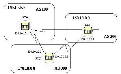
RTA#
router bgp 100
neighbor 150.10.20.2 remote-as 300
network 150.10.0.0
RTB#
router bgp 200
neighbor 160.10.20.2 remote-as 300
network 160.10.0.0
RTC#
router bgp 300
neighbor 150.10.20.1 remote-as 100
neighbor 160.10.20.1 remote-as 200
network 170.10.00
Note that you do not need network 150.10.0.0 or network 160.10.0.0 in RTC unless you want RTC to also generate these networks on top of passing them on as they come in from AS100 and AS200. Again the difference is that the network command will add an extra advertisement for these same networks indicating that AS300 is also an origin for these routes.
An important point to remember is that BGP will not accept updates that have originated from its own AS. This is to insure a loop free interdomain topology.
For example, assume AS200 above had a direct BGP connection into AS100. RTA will generate a route 150.10.0.0 and will send it to AS300 then RTC will pass this route to AS200 with the origin kept as AS100, RTB will pass 150.10.0.0 to AS100 with origin still AS100. RTA will notice that the update has originated from its own AS and will ignore it.
IBGP is used if an AS wants to act as a transit system to other ASs. You might ask, why can't we do the same thing by learning via EBGP redistributing into IGP and then redistributing again into another AS? We can, but IBGP offers more flexibility and more efficient ways to exchange information within an AS; for example IBGP provides us with ways to control what is the best exit point out of the AS by using local preference (will be discussed later).
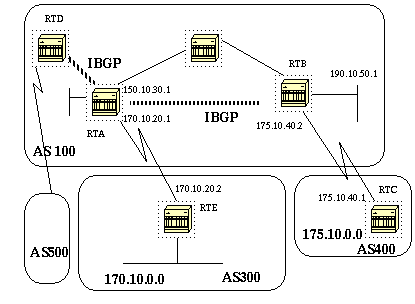
RTA#
router bgp 100
neighbor 190.10.50.1 remote-as 100
neighbor 170.10.20.2 remote-as 300
network 150.10.0.0
RTB#
router bgp 100
neighbor 150.10.30.1 remote-as 100
neighbor 175.10.40.1 remote-as 400
network 190.10.50.0
RTC#
router bgp 400
neighbor 175.10.40.2 remote-as 100
network 175.10.0.0
An important point to remember, is that when a BGP speaker receives an update from other BGP speakers in its own AS (IBGP), the receiving BGP speaker will not redistribute that information to other BGP speakers in its own AS. The receiving BGP speaker will redistribute that information to other BGP speakers outside of its AS. That is why it is important to sustain a full mesh between the IBGP speakers within an AS.
In the above diagram, RTA and RTB are running IBGP and RTA and RTD are running IBGP also. The BGP updates coming from RTB to RTA will be sent to RTE (outside of the AS) but not to RTD (inside of the AS). This is why an IBGP peering should be made between RTB and RTD in order not to break the flow of the updates.
After BGP receives updates about different destinations from different autonomous systems, the protocol will have to decide which paths to choose in order to reach a specific destination. BGP will choose only a single path to reach a specific destination.
The decision process is based on different attributes, such as next hop, administrative weights, local preference, the route origin, path length, origin code, metric and so on.
BGP will always propagate the best path to its neighbors.
In the following section I will try to explain these attributes and show how they are used. We will start with the path attribute.
(End of section 1)